21
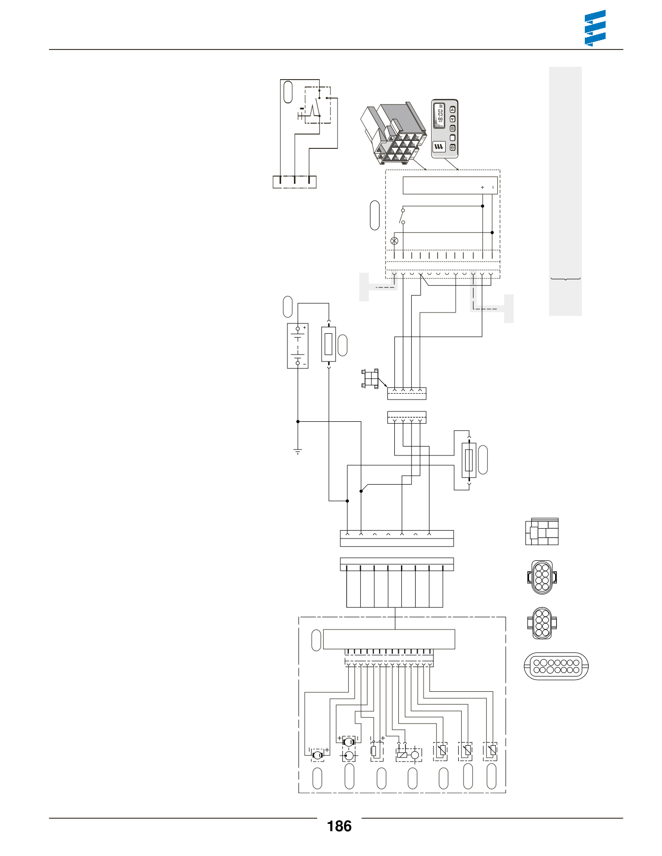
Heater Diagnostics
M
1 2 3 4 5 6 7 8 9 10 11 12 13 14
B2
P
M
Optional
e)
Optional
Optional
f)
Red
2.7.1
Yellow
Brown
Brown
Blue
Blue/White
Yellow
Red
Red/Yellow
Red
Brown
4 3 2 1
b)
a)
d)
c)
4 3 2 1
Brown
Red
Red
DIAG
TRS
Brown
a) Power frombattery“+”.
b) Switchcontrol toheater.
c) Power frombattery“-”.
d)Diagnostics fromheater.
e)Tovehicledimmer switch for lightdisplay.
f)Tovehicle ignitionaccessories for continuous
operationof heater.
12 11 10 9 8 7 6 5 4 3 2 1
3.2.9
5.1
2.7
Red
Brown
Black/Red
Green
Blue/White
Blue
Yellow
Black/White
S1
B1
1
2
3
4
5
6
7
8
8 7 6 5 4 3 2 1
1 2
3 4
Brown
Black
Brown
Violet
Brown
White
Green
Green
Red
Red
Blue
Blue
Brown
Blue
1.1
2.12
1.2
2.2
1.5
1.13
1.12
h)
S1
B1
B3
2.1
B2
2 4 6 8
1 3 5 7
8 6 4 2
7 5 3 1
1 3 5 7 9 11 13
87
87a 85
30
86
2 4 6 8 10 12 14
HydronicD5SC 12Volt
Model 25 2098 05
25 2219 05
25 2257 05
WiringHarnessP/N:
20 2900 70 05 03
(CA0 60 503)
Internal FMP
NoBlower Relay
1.1 Blower motor
1.2 Glow pin
1.5 Overheat sensor
1.12 Flame sensor
1.13 Temperature sensor
2.1 Control unit
2.12 Water Pump
2.2 Fuel metering pump
2.7 20 amp/12Vmain fuse
15 amp/24Vmain fuse
2.7.1 5 amp fuse
3.12 Push/Pull switch
3.2.9 7 day timer
5.1 Battery
Red
K(15)
15(K)
Yellow
Brown
31
0
3.1.1
Push/Pull switch
7 day timer
3.12


