18
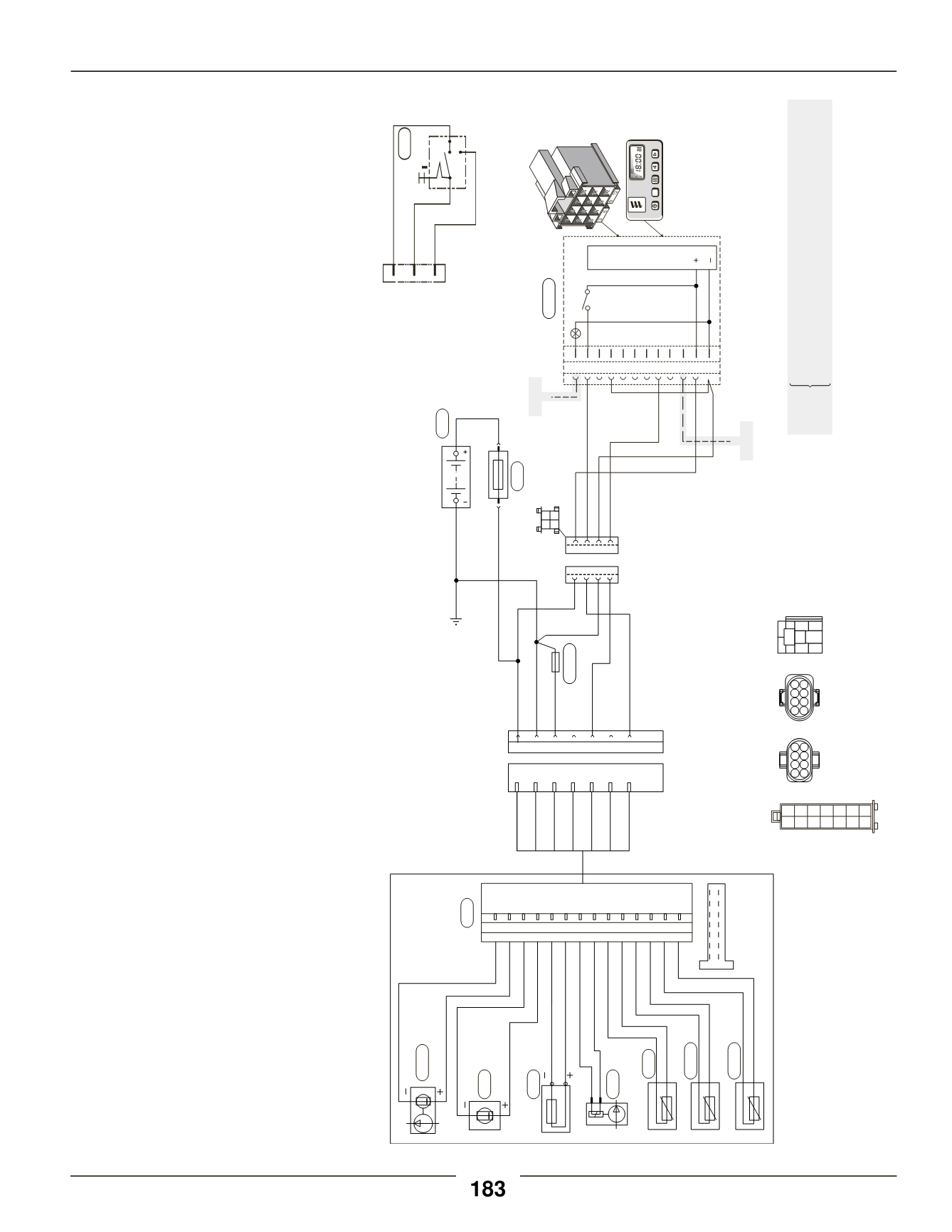
Heater Diagnostics
HydronicD4SC 12Volt
Model 25 1917 01
WiringHarness P/N:
202900700401
(CA060401)
1.1 Blower motor
1.2 Glow pin
1.5 Overheat sensor
1.12 Flame sensor
1.13 Temperature sensor
2.1 Control unit
2.12 Water Pump
2.2 Fuel metering pump
2.5.8 Blower lock out resistor
2.7 20 ampmain fuse
3.12 Push/Pull switch
3.2.9 7 day timer
5.1 Battery
Red
K(15)
15(K)
Yellow
Brown
31
0
3.1.1
Push/Pull switch
7 day timer
3.12
Optional
Brown
e)
Optional
Optional
f)
M
M
Yellow
Yellow
Red
Brown
Brown
Brown
Blue
Blue/White
Blue/White
DIAG
TRS
a) Power frombattery“+”.
b) Switchcontrol toheater.
c) Power frombattery“-”.
d)Diagnostics fromheater.
e)Tovehicledimmer switch for lightdisplay.
f)Tovehicle ignitionaccessories for continuous
operationof heater.
12 11 10 9 8 7 6 5 4 3 2 1
4 3 2 1
1
2
3
4
5
6
7
8
1
2
3
4
5
6
7
8
1 2
3 4
b)
a)
d)
c)
4 3 2 1
2 4 6 8
1 3 5 7
8 6 4 2
7 5 3 1
P
3.2.9
2.5.8
5.1
2.7
Red
Red
Red
Brown
Red
Brown
Green
LightGreen
Blue/White
Black
Blue
S1
B1
S1
B1
B2
B2
B3
2.1
2.12
1.1
1.2
2.2
1.5
1.13
1.12
Violet
Brown
LightBrown
Black
White
Brown
Green
Green
Red
Red
Blue
Blue
Brown
Blue
14 13 12 11 10 9 8 7 6 5 4 3 2 1
1 3 5 7 9 11 13
2 4 6 8 10 12 14
2 4 6 8 10 12 14
1 3 5 7 9 11 13
87
87a 85
30
86
Red/Yellow


