25
Maintenance / Troubleshooting / Repair
35
30
25
20
15
10
5
0
0
20
40
60
80
100
120
3000
2750
2500
2000
2250
1000
1250
1750
1500
750
0
-50 0 50 100 150 200 250 300 350 400 450 500 550
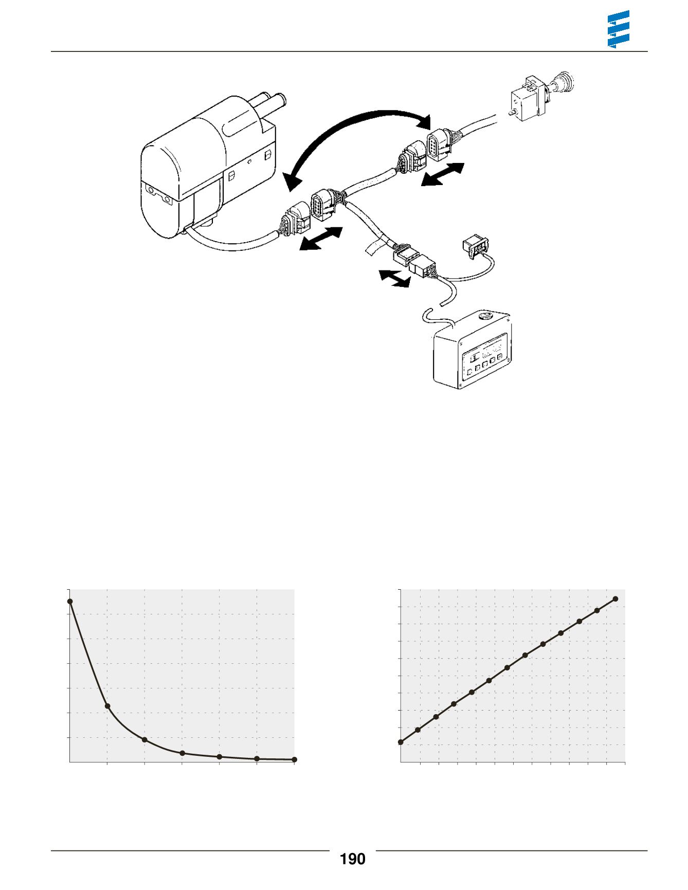
HookUp
• Disconnect themain harness from heater and insert
adapter cable harness between them.
• Connect adapter cable to the cable loom of the Fault
code retrieval device.
HYDRONIC
5 adapter for
Fault code retrieval device
P/N 12V 20 2900 70 50 28
(CA0 05 028)
TestValues
Resistance
Metering pump
approx. 10
Ω
for 12 volt heater; approximately 36
Ω
for 24 volt heater
GlowPin
approx. 0.9
Ω
Checking the sensors
To check the sensors, measure the resistance at current temperature, see following diagrams:
Temperature sensor
Overheating sensor
Flame sensor
Temperature (°C)
Temperature (°C)
Resistance (Kohms)
Resistance (ohms)
R> 2
Ω
= open circuit
R< 50
Ω
= short circuit
R> 3400
Ω
= open circuit
R< 50
Ω
= short circuit
Fault code retrieval device
P/N 12V 20 2900 70 50 20
(CA1 05 020)


