Once ignition is successful the following operations
take place:
• Heater runs in high heat mode and the temperature is
monitored at the heat exchanger.
• Once coolant reaches 80°C (176°F) the heater
automatically switches to low heat mode and continues
to run.
• If coolant temperature drops to 75°C (167°F) the heater
will automatically switch back to high heat mode.
• If the coolant temperature continues to rise, the heater
will automatically switch off once temperature reaches
86°C (187°F).
• Thewater pumpwill continue to circulate coolant to allow
the heater tomonitor engine temperature.
• The heater will automatically re-start once coolant
temperature reaches 75°C (167°F).
• The heater continues to run as described above until it is
switched off, either manually, automatically by a timer or
heater malfunction shutdown.
Note:
If the heater should shut down due to flame
out while in runningmode, it will automatically
attempt one restart. If successful, it will contin-
ue to run. If not, it will shut down completely
with a cool-down cycle.
Note:
During operation the heater continually sens-
es the input voltage from the batteries. If the
input voltage drops to approximately 10.5
volts or rises above 16 volts the heater will
automatically shut downwith a cool-down
cycle, and display a fault codewhen using a
multifunction timer.
15
Heater Operation
Push/Pull Switch
Note:
If theheater fails tostart the first time itwill
automaticallyattempt asecondstart. If unsuc-
cessful, theheaterwill shut downcompletely.
Note:
On initial start up theheatermay require sever-
al start attempts to self prime the fuel system.
Upon completion of installation prepare the heater as follows:
• Check all fuel, electrical and plumbing connections.
• Refill the engine coolant.
• Bleed air from the coolant system by loosening the bleed
screw on top of the heater to allow air to escape.
• Loosen rad cap and run engine to allow air to be purged.
• Top up engine coolant.
Once switched on the following sequence occurs:
• Control unit does a systems check ( flame sensor, glow
pin, motors, temperature sensor, safety thermal sensor
and various other control unit checks).
• Water pump starts circulating coolant fluid.
• Combustion air blower comes on.
• Glow pin begins to preheat 20-50 secs.
• Metering pump starts and combustion air blower speeds
up gradually.
• Once ignition takes place the flame sensor alerts the
control unit and the control unit shuts off the glow pin
(ignition time: 1.5 - 2minutes).
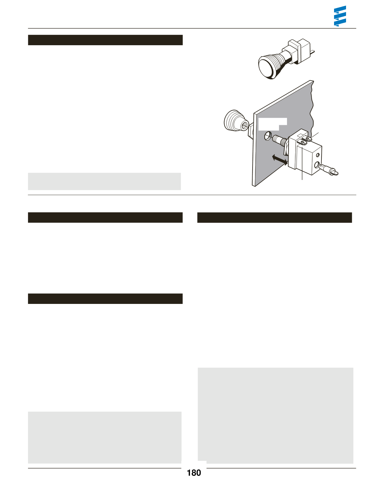
• Mount switch in a locationwhere it is easily accessible.
• Mount using hardware supplied.
• Connect the switch harness to the connector at the heater
and run the harness to the switch location.
• Cut harness to length at the switch and install terminals.
• Connect wiring as shown.
14.5mm
9/16”
K (15)
15 (K)
31
Note:
Wired as above the switch light glows when
pulled out and is off when pushed in.
ControlWiring
Push/Pull Switch
Brown- 31
Power from battery “-”
Red- K(15)
Power from battery “+”
Yellow-15(K)
Switch control to the heater
Blue/White
Diagnostic from heater (disregard - tape
end and tie off to the side)
Heater Operation
Start Up
Pre-Start Procedures
Running
Ø
Ø


