SomeHydronic water heaters (2219) typically have the fuel
metering pumpmounted inside the unit.This is to reduce
installation time and to protect the pump from corrosion.
Some versions have an external fuel metering pump.Refer to
graphics for connections and specifications.
All parts necessary to do the installation are included in the
kit as shown.
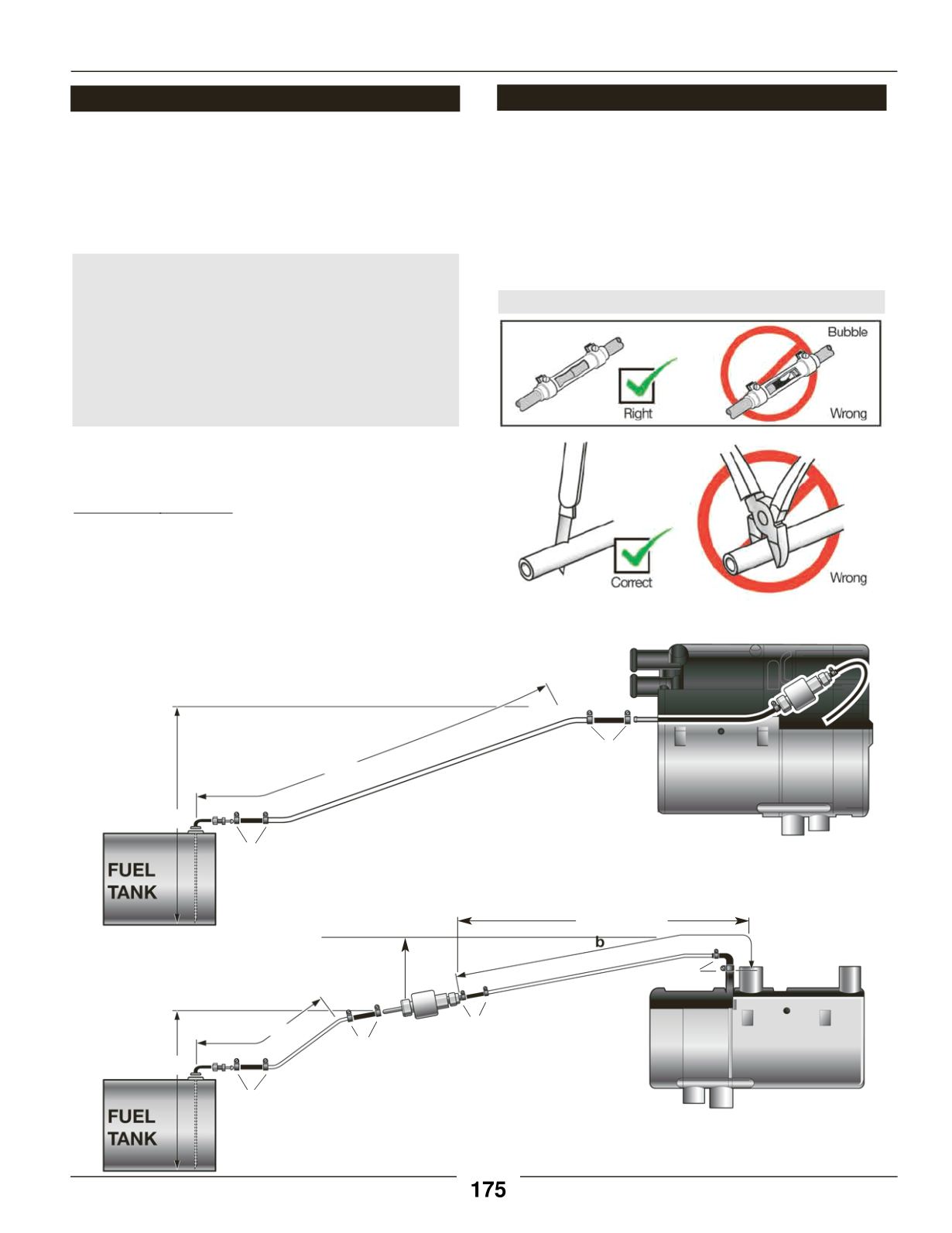
Note: For 25 2219 and similar “SC”Heaters:
Fuel line limitsmust not be exceeded.
Ensure that the following conditions aremet.
Hydronic heater must bewithin a height of 76cm
(2’6”) from the bottom of the fuel pick-up pipe.
Fuel-metering pumpmust bewithin a total
distance of 200 cm (6’6”) from the fuel pick-up pipe.
If the above conditions cannot bemet, a heater with
external fuel metering pumpmust be used.
10
Installation Procedures
Fuel System
Note:
Butt joints and clamps on all connections.
1
2
Max. 76cm (2’6”)
Max. 2M (6’6”)
4
3
5
5
4
3
6
• Route fuel lines from the fuel pick-up pipe to the heater.
• Use only fuel lines provided.
• Other sizes or types of fuel linesmay inhibit proper fuel
flow.
• Make proper butt joints using clamps and connector
pieces as shown.
• Use a sharp utility knife to cut plastic fuel lines to avoid
fuel line pinching.
HydronicHeater
1. Fuel Pick-Up Pipe
2. Fuel PipeReducer
3. 9mmClamp
4. 3.5mmRubber Connector
5. 2.0mmWhite Plastic Fuel Line
6. Fuel Metering Pump
7. 1.5mWhite Plastic Fuel Line
6
Max. 76cm (2’6”)
2 4
3
4
3
4
4
3
3
Max. 2M (6’6”)
Max. 6M (19.8’)
1
7
Fuel SystemTolerances
Max. 2M (6.5’)
Fuel Line
“SC”Models
25 2219 05
and similar
“S”Models
25 2217 05
and similar


