E-SERIES
(May, 2004)
13
STATEMENTSOFCONFORMITY
105 Thestatementsbelowareapplicable to the following
incompletevehicle typesexceptwhencompletedasa
schoolbus,and if theGVWR isbetween3629kg [8000
lb] and6373kg [14,050 lb] inclusive:
• IncompleteE-SeriesVanorWagon
• E-SeriesCutaway
• E-SeriesBasic (Stripped) Chassis
This vehicle, when completed, will conform toStandard
105, Hydraulic andElectricBrakeSystems, if:
• No alterations, modifications, or replacements are
made to the following:
– Service or parking brake system
– Antilock brake system
– Vacuum system
– Wheels and tires
– Brake system indicator lamp andwiring
– Brake system reservoir labeling
– Suspension rideheight or spring rate
– Hydro-boost system
– Power steering pump and lines if usedwithHydro-
boost
– Engine belt drive system
– Wheelbase
• No additional sound deadener or rust proofing
material, that may be applied to the vehicle, can
interferewith proper parking brake cable function.
• No part of add on equipment, i.e. toolboxes, flat
bed attaching brackets, etc., can interfere with the
movement of parking brake cables or air flow to rear
brakeassembly.
• Any removal of aFord body or chassis component is
accompaniedby the additionof equal weight.
• E-Series Cutaway and Basic (Stripped) Chassis
vehicles conform to theminimumSUBweights found
inTableB, page15.
• The maximumGAWRs and GVWR, as identified on
the cover of this document, are not exceeded with
the vehicle weight at Unloaded Vehicle Weight +
Passenger Load (P). (See E-Series Passenger Load
chart on this page.)
• The service or parking brake pedal assembly
operation is not restricted by any alteration or added
components.
• The SUB horizontal center of gravity must be at or
forward of the rear axle centerline for the following
vehicles:
- E-350/450Basic (Stripped) Chassis
- E-350Super DutyCutaway (DRW)
- E-450Super DutyCutaway
105
(Continued)
The horizontal center of gravity for theSUB is:
– At or forwardof the rearaxlecenterline.Thevertical
centerof gravity for thecompletedvehicleatGVWR
CGv (Equation C) must not exceed 48.0 inches
whenmeasured from theground.
– Behind the rear axle centerline.The vertical center
of gravity for the completed vehicleat GVWRmust
fall within the appropriate range determined from
Table E page 16. The value of CGh (Equation D),
whichapproximates thehorizontal center of gravity
of the completed vehicle, is used in Table E to
determine the vertical center of gravity limits for
the completed vehicle.The valueof CGv (Equation
C) which approximates the vertical center of
gravityof the completed vehiclemust fall within the
appropriate range determined fromTableE.
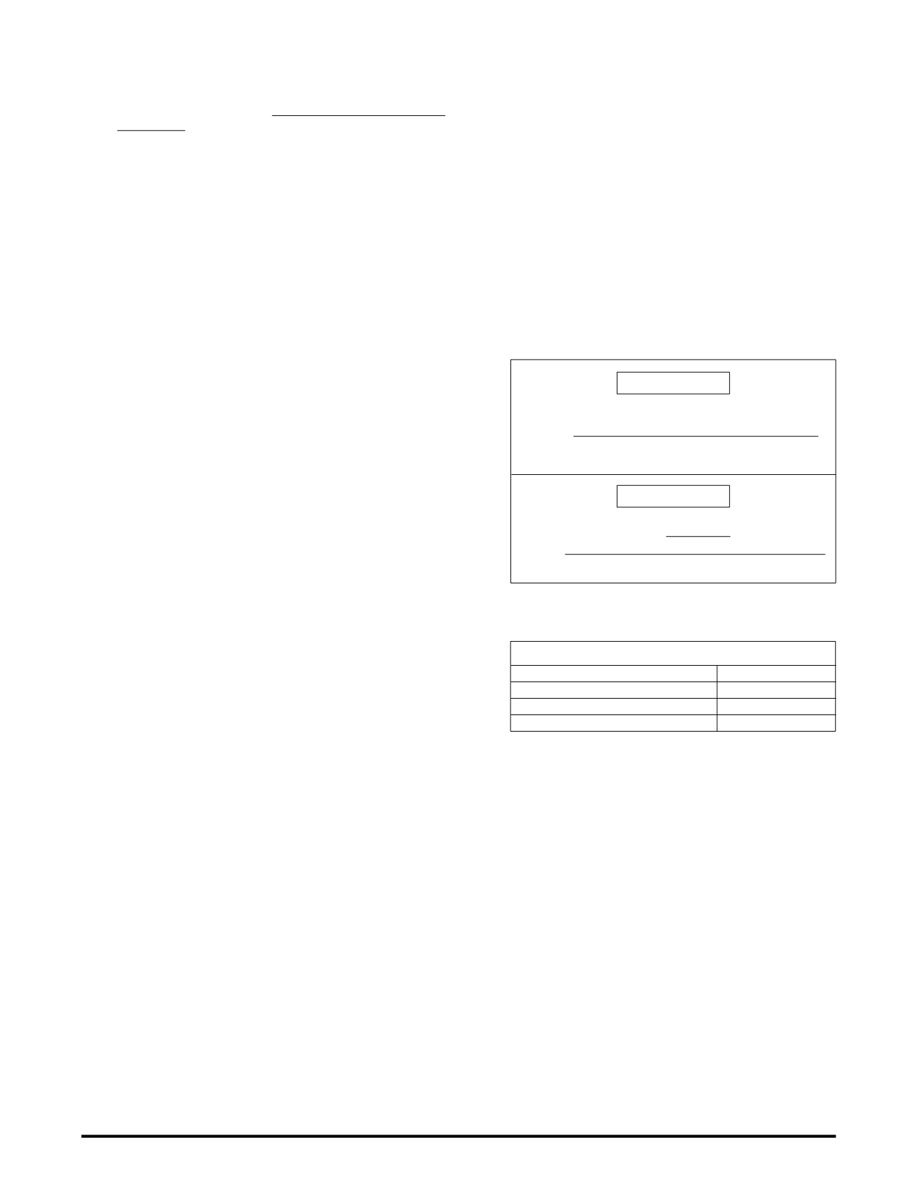
EQUATIONC
CG
v
=
CG
vb
W
b
+CG
vc
(
W
c
+W
l
)
+25P
GVWR
EQUATIOND
CG
h
=
GVWR
(
W
rb
+W
rc
+
+W
rl
)
xWB
(
)
P xCG
hp
WB
E-SERIESPASSENGERLOAD
GVWR [lb]
P [lb]
0 - 7716
397
7717 - 10,000
400
10,001 - 19,000
500


