E-SERIES
(May, 2004)
10
STATEMENTSOFCONFORMITY
102 Thestatementsbelowareapplicable toall incomplete
vehicle typesexcept theBasic (Stripped)Chassis:
This vehicle, when completed, will conform toStandard
102, Transmission Shift Lever Sequence, Starter
Interlock, and Transmission Braking Effect, if no
alterationsoradjustmentsaremade to the transmission,
shift cable, transmission outer shift lever, shift cable
bracket, vacuum tubes, vacuum pump system, brake-
shift interlock system, starter interlock system, wiring
circuit from the interlockswitch to thepower source, and
transmission gear selector indicator (PRNDL).
If an auxiliary transmission is added to this vehicle, it
must conform to the requirements of thisStandard.
102 Thestatementsbelowareapplicable to the following
incompletevehicle type:
•
E-SeriesBasic (Stripped) Chassis
This vehicle, when completed, will conform toStandard
102, Transmission Shift Lever Sequence, Starter
Interlock, andTransmissionBrakingEffect if:
• No alterations or adjustments are made to the
transmission, shift cable, transmission outer shift
lever, shift cable bracket, vacuum tubes, vacuum
pumpsystem, brake-shift interlocksystem, thestarter
interlock system, andwiring circuit from the interlock
switch to thepower source.
• The E-Series Basic (Stripped) Chassis is equipped
witha temporary transmissiongear selector indicator
(PRNDL)whichmust be replacedwith thecluster and
transmission gear selector indicator (PRNDL) that is
shippedwith thevehicle in thedunnageboxandmust
be installed and adjusted following the instructions
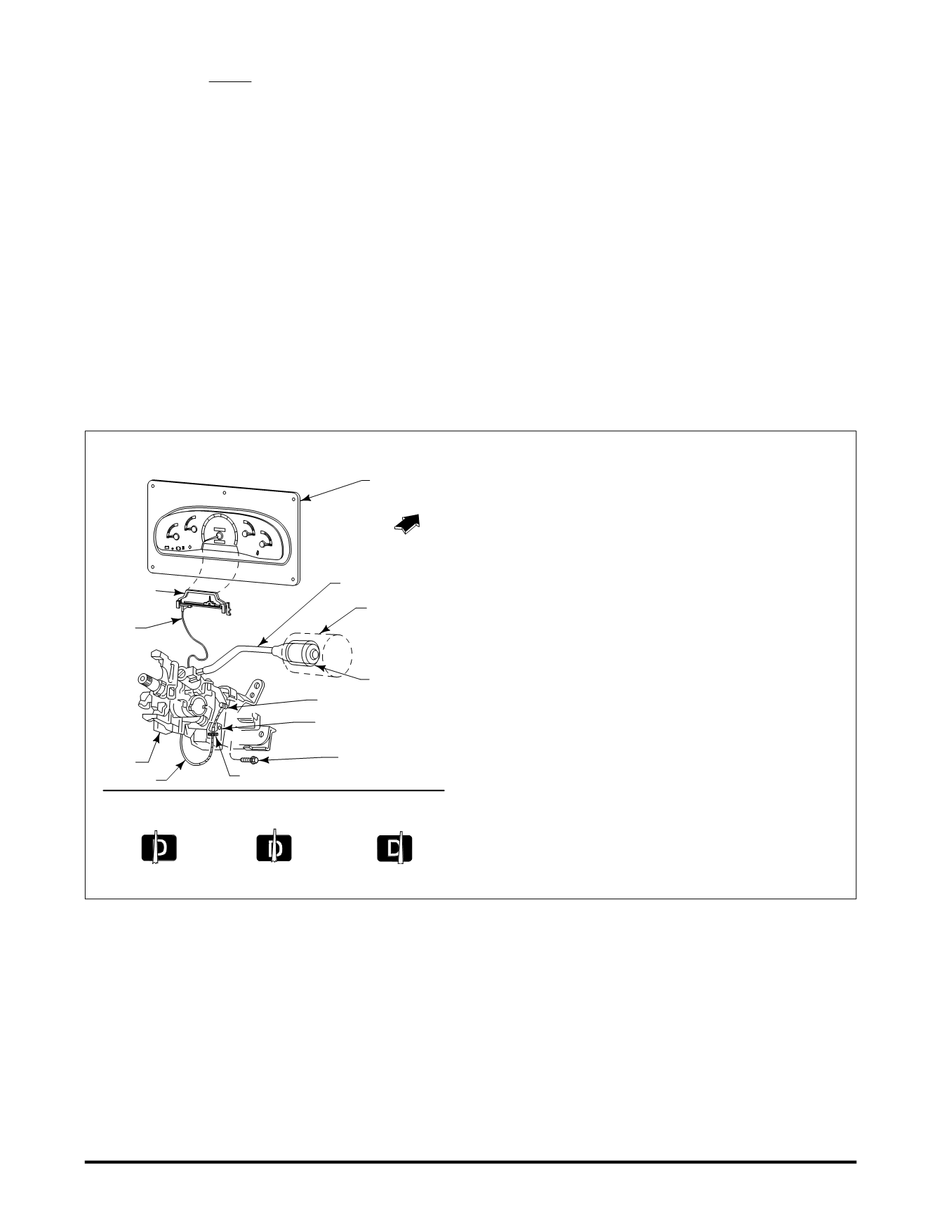
and specifications shown in the figurebelow.
If an auxiliary transmission is added to this vehicle, it
must conform to the requirements of thisStandard.
1.Route the cable after the instrument cluster is installed in
the vehicle. Do not kink the cable. Do not bend the cable
to a radius less than 4.5 inches. Route the cable from
the cluster in a counter-clockwise direction, under the
steering column, using the screw provided. Do not wrap
thecablearound thesteeringcolumn.Thesteeringcolumn
shroud installation should not affect the cable routing
or function.
2.Pull on the cable end loop for a functional check. The
cable should operatewith a similar effort as required prior
to routing. Then place the cable loop on the shift lever
retainer pin.
3.Rotate the column shift lever clockwise until it bottoms
out in first gear.
4.Rotate thecolumnshift levercounter-clockwise3detents for
Overdrive “Oval D” position forTorqShift™ transmissions.
5. Install a 3 pound weight, as defined in this illustration, on
the end of the column shift lever.
6.Center thepointer in themiddleof the “Oval D” positionby
rotating the thumbwheel.
7.Remove the 3 pound weight. The pointer must be within
the tolerances as defined in this illustration.
8.After the steering column shrouds are installed, the
transmissiongear selector indicator (PRNDL) systemmust
be checked for proper operation.
INSTALLATIONOFGEARSELECTOR INDICATOR (PRNDL) FORE-SERIESBASIC (STRIPPED) CHASSIS
00000
0
18
H
000
0
50
60
70
80
90
100
10
20
30
40
0
M
PH
UNLEADEDFUELONL
Y
BRAKE
SERVICE
ENGINE SOO
N
F
H
C
E
P R N
1
INSTRUMENT
CLUSTER
CABLE
STEERING
COLUMN
CABLE
THUMBWHEEL
COLUMNSHIFT
LEVER
FRONTOF
VEHICLE
CABLERETENTION
BRACKET
SHIFT LEVER
RETAINERPIN
N800705SCREW
TORQUE20-29 IN.LB.
[ ] ALLDIMENSIONSARE INCHES
3.0-3.5 LB.WEIGHT
HANDTOOL
[2.375] ±0.25DIA.
(PRNDL)
HOLE: [1.125] DIA.
X [2.188] 0.25DEEP
(PRNDL) ADJUSTMENTTOLERANCE
+
+
RIGHT LIMIT
LEFTLIMIT
TARGET
D
±


