


 2 / 2
2 / 2
TITLE :
# DRAWING :
REV :
PAGE :
DATE :
DRAW. :
THE INFORMATION, TECHNICAL DATA AND STANDARDS
DESCRIBED HEREIN ARE THE EXCLUSIVE PROPERTY OF DEMERS
AMBULANCES AND/OR CONTAIN PROPRIETARY RIGHTS OF
OTHERS AND ARE NOT TO BE USED OR DISCLOSED TO OTHERS
WITHOUT THE WRITTEN AGREEMENT OF DEMERS AMBULANCES.
# ASS :
Y. DUBÉ
OPTION "B"
OPTION "B"
OPTION "B"
OPTION "B"
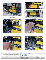
7
9
10
11
8
Crimp and heat shrink diode assembly.
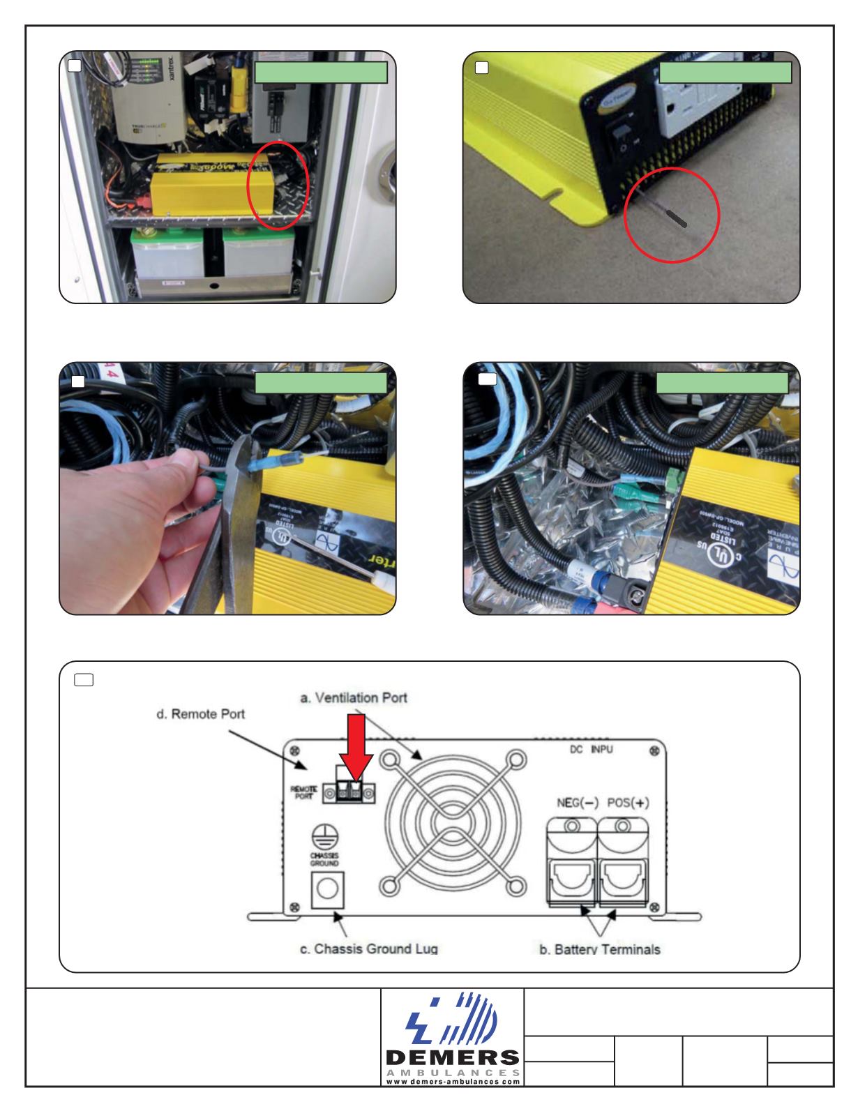
Install wire in connector.
See below schematic.
1 - Cut wire and insulate on inverter end.
2 - Skin wire on the other end and reroute behind
to go to the other side of the inverter.
INVERTER IGNITION CIRCUIT CORRECTION
2/2
# 01073
2016-11-18
0