


 2 / 3
2 / 3

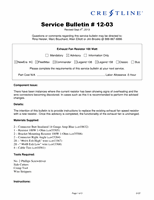
1.
Depending on configuration, the ambulance Electrical Control Center (ECC) board may have one or two
resistors. For boards with two resistors, we want to replace
green wires. The wires are labelled “#64A Exh High” and “#64B Exh Low.”
Board Type 1
2.
Remove cover on wire ducting and cut cable ties containing the wires leading to the resistor.
3.
Cut the existing resistor wires back far enough to eliminate any discoloured insulation.
4.
Remove and discard old resistor and mounting legs, keep mounting screws.
5.
Install new resistor and mounting legs in place of old resistor.
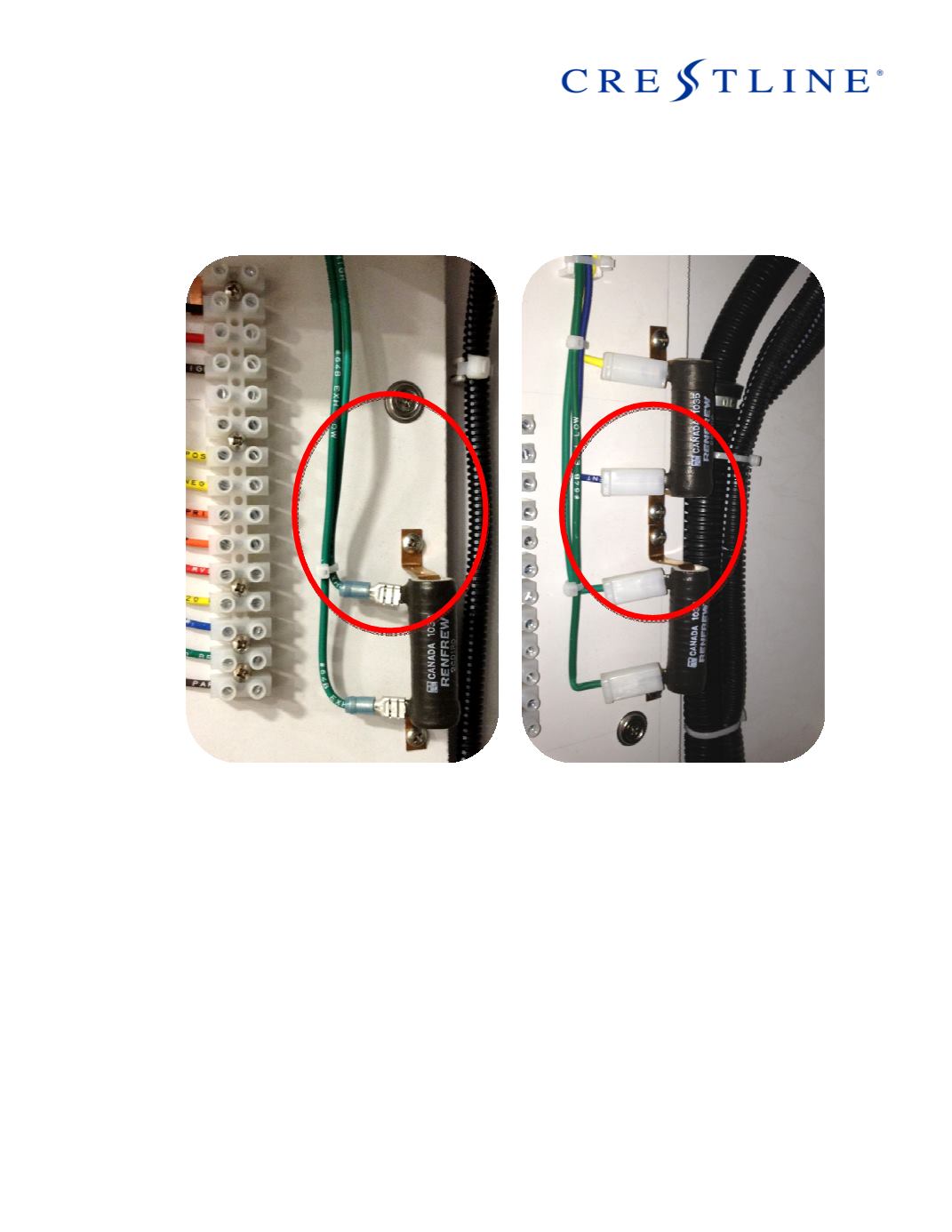
Note: Depending on wiring and board
mounting the larger resistor. For example, in the right hand picture above, the intake and exhaust
resistors may be installed vice-versa and you will need to move the intake resistor to the upper p
6.
Run wires from new resistor to the cut wires from old resistor inside the wire ducting.
7.
Cut provided wire on new resistor to length required.
8.
Strip the wires and connect new wires to wires cut earlier using supplied butt connectors making sure to
match wires labels (64A -> 64A, 64B
9.
Use the supplied cable ties to tie the wires back to the ECC board.
10.
Replace wire duct cover. Resistor change is now complete.
Page 2 of 3
the resistor (circled in red) with the two
Board Type 2
layout, the resistor may have to be moved to accommodate
-> 64B).
0137
osition.