


 3 / 3
3 / 3
62725-62790 Crestline Ambulance Isolator Modification
3
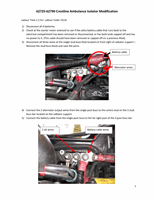
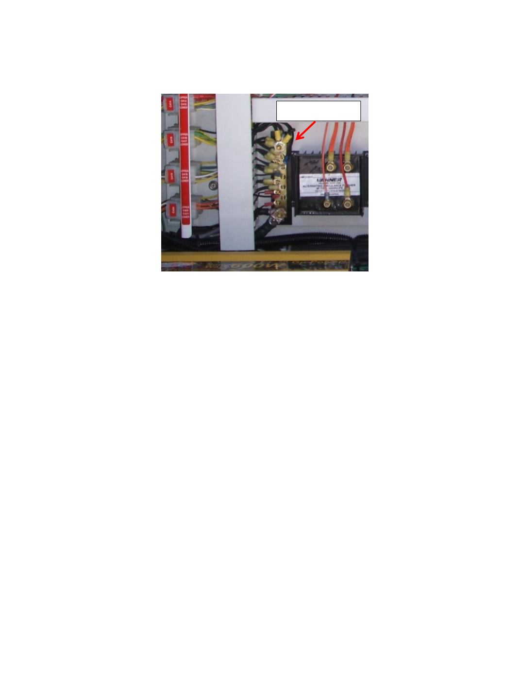
8)
Using the appropriate electrical connectors, attach a black extension wire to the black ground
wire from the relay, then route and attach it to the ground buss in the electrical compartment.
9)
Separate and cap the purple boost and white status wires from relay (not used)
10)
Re-connect all batteries
11)
Check Battery Voltage at Main and Auxiliary terminals of solenoid relay (be sure all batteries are
above 12.6 V).
12)
Start engine, check for charging voltage/amperage on the main and secondary side of isolator
relay.
The red light on the isolator solenoid comes on when the relay is connected – alternator charge
voltage/amperage will be the same on both main and secondary solenoid terminals.
When battery voltage drops below 12.7 V on either battery bank, the relay will disconnect and
the red light will go out.
Note: The Relay will not disconnect until one or both battery banks drop below 12.7 for more
than 60 seconds.
The red light indicator at the base of solenoid is turned on only when the auxiliary and main
batteries are connected.
The solenoid will only re-connect when the starting batteries reach 13.2 V (there may be a time
delay for up to 60 seconds before the relay re-connects).
Ground wire buss