CRSeriesTDR
SolvingYourTimingRequirements Since 1922
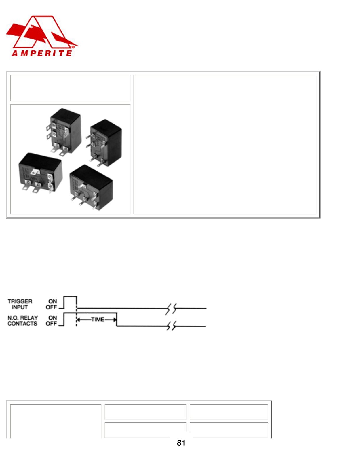
CRSeriesTDR
…Solid state analog circuitry
…Triggereddelay on release timingmode
…Compact size
…Relay outputwithSPST orSPDT contacts
…Timing selection: Fixed orknob adjustable
…Numerousmodels timing from 1 sec. to 600 secs.
…ULFile #E96739 (M)
…CSAFile #LR62586
TimingMode:
Input voltagemust be applied continuously to operate the internal relay. Relay contacts
transferwhen the trigger input terminal is activated. The timing cycle beginswhen the trigger input
terminal is deactivated.When the timing cycle is completed the relaywill de-energize. The timing cycle
may be reset to zero during the timing cycle by reactivating the trigger input terminal.
TimingDiagram:
Contact Information:
Arrangement:
1 formA (SPSTNormally open) -DiagramA
1 formB (SPSTNormally closed) -DiagramA
1 formC (SPDT) -DiagramB
Max. switching power 30W, 50VA
Max. switching voltage 60VDC, 125VAC
file:///S|/DWGS/700/750000/oemTIFF/Chris006.XSM/1.htm (1 of 4) [12/3/20029:12:36AM]


